I fixed my Nano Controller (Sort of) // PCOMP W2

Sep 16, 2024

Fixing My Short-Circuited Microcontroller

Last week, I short-circuited my microcontroller and had to go through the process of troubleshooting and repair with Robert. Here’s what we did:

1. Identifying the Problem

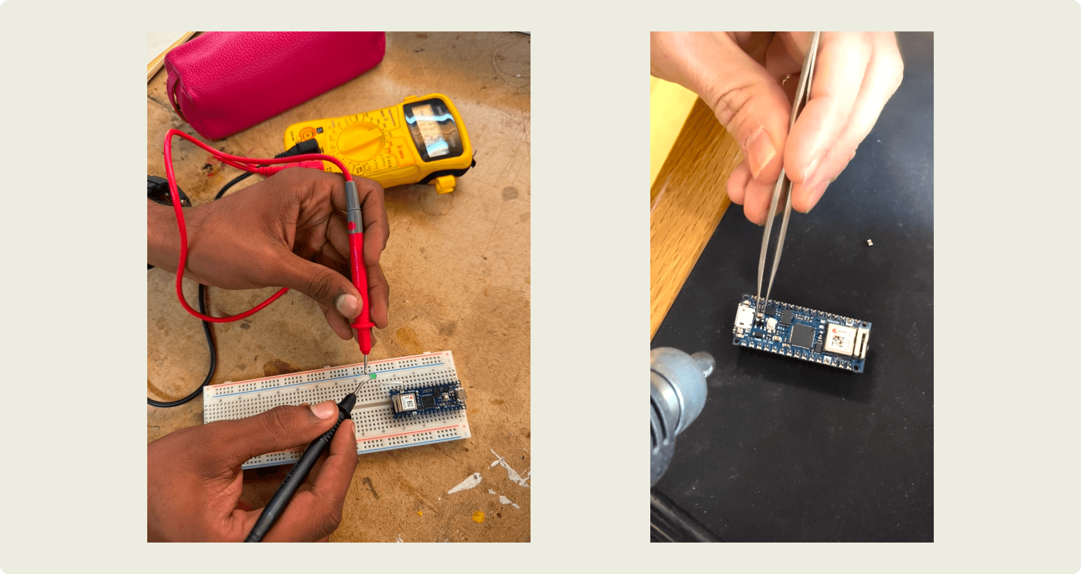
We began by checking for continuity across different points on the microcontroller using a multimeter. Initially, we thought two components near the ground pin and USB input were resistors, but we later realized they were capacitors that had failed.

2. Analyzing the Schematic

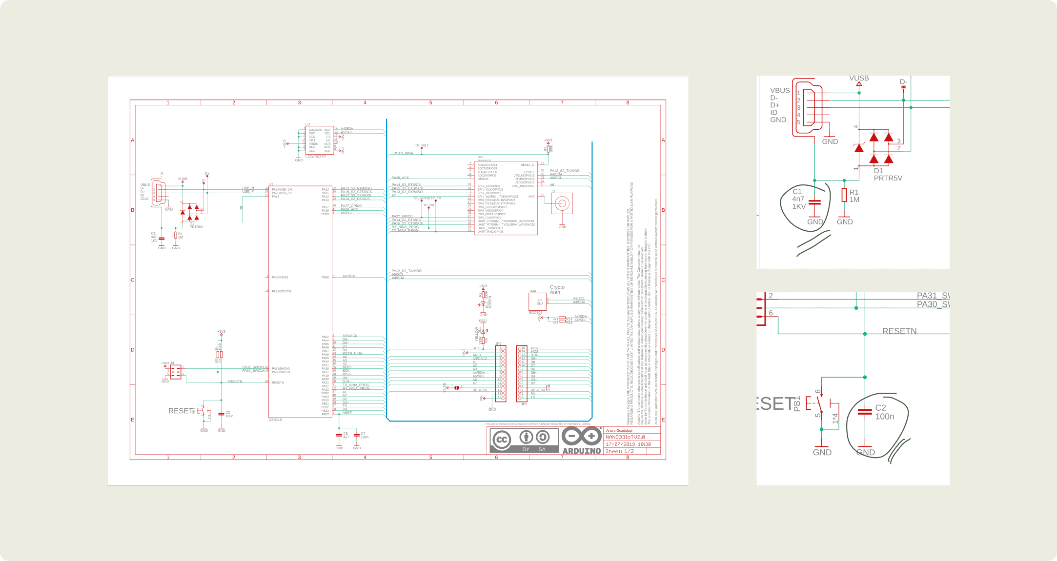
Using the schematic (shown below), we located the problematic components near the ground pin and USB input. This helped us narrow down the exact capacitors that needed replacing.

3. Replacing the Capacitors

After identifying the faulty capacitors, we matched their values with what was available in the lab. We replaced them, but at first, the microcontroller still overheated. This led us to reevaluate our approach and find better capacitor matches.

4. Partial Success and Lessons Learned

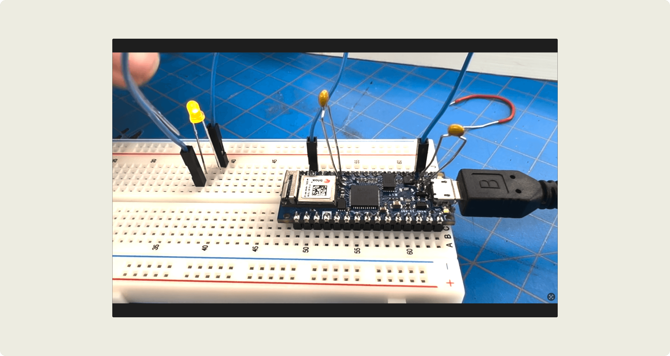
Once the capacitors were replaced, the microcontroller powered up again, but the lights began flickering. We believe this was due to the capacitors not holding the exact amount of charge required by the Arduino Nano. While not perfect, this was a valuable learning experience in reading schematics and troubleshooting hardware.

Lab 1 : Programming the Arduino

This Lab was straightforward, learning C syntax was new but with the Arduino website reference I was able to manage.

Below is the code for Lab 1 :

void setup() {
  pinMode(2, INPUT);    // set the pushbutton pin to be an input
  pinMode(3, OUTPUT);   // set the yellow LED pin to be an output
  pinMode(4, OUTPUT);   // set the red LED pin to be an output
}

void loop() {
   // read the pushbutton input:
   if (digitalRead(2) == HIGH) {
     // if the pushbutton is closed:
     digitalWrite(3, HIGH);    // turn on the yellow LED
     digitalWrite(4, LOW);     // turn off the red LED
   }
   else {
     // if the switch is open:
     digitalWrite(3, LOW);     // turn off the yellow LED
     digitalWrite(4, HIGH);    // turn on the red LED
   }
 }

Lab 2 : Analog Input

Easy peeezy no trouble at all. I'm also talking through the process in the video so do watch.

  const int LedPin = 9; // Digital 1/o pin the LED is attached to
  int Analogvalue = 0; // value that the potentiometer is gonna read 
  int Brightness = 0; // brightness of the LED 

void setup() {
  // intitialize serial comms at 9600 bps: 
  Serial.begin(9600);
  pinMode(LedPin, OUTPUT); 

}

void loop() {
    analogValue = analogRead(A0);      // read the pot value
    frequency = (analogValue /4) * 10; // divide by 4 to fit in a byte, multiply by 10 for a good tonal range
    tone(pinNumber, frequency);        // make a changing tone on the speaker
    Serial.println(brightness);        // print the brightness value back to the serial monitor
}

Lab 2.1 : FSR

This lab was also pretty straightforward what I also enjoyed was figuring out how the ports relate to each other on from Arduino nano and Arduino uno.

const int redLED = 10;     // pin that the red LED is on
const int greenLED = 9;    // pin that the green LED is on
int rightSensorValue = 0;  // value read from the right analog sensor
int leftSensorValue = 0;   // value read from the left analog sensor

void setup() {
  Serial.begin(9600);
  pinMode(redLED, OUTPUT);
  pinMode(greenLED, OUTPUT);
}

void loop() {
  // Read the right FSR on analog pin 0
  rightSensorValue = analogRead(A0);
  
  // Read the left FSR on analog pin 1
  leftSensorValue = analogRead(A1);

  // Map FSR values to LED brightness
  int rightBrightness = map(rightSensorValue, 0, 1023, 0, 255);
  int leftBrightness = map(leftSensorValue, 0, 1023, 0, 255);

  // Control LEDs
  analogWrite(redLED, rightBrightness);
  analogWrite(greenLED, leftBrightness);

  // Print debug information
  Serial.print("Right FSR: ");
  Serial.print(rightSensorValue);
  Serial.print(", Right LED: ");
  Serial.print(rightBrightness);
  Serial.print(" | Left FSR: ");
  Serial.print(leftSensorValue);
  Serial.print(", Left LED: ");
  Serial.println(leftBrightness);

  delay(100);
}

Lab 3.0 : PushButton Change State

This lab was also pretty straightforward what I also enjoyed was figuring out how the ports relate to each other on from Arduino nano and Arduino uno.

// state of the button last time you checked
int lastButtonState = LOW;    
int buttonPresses = 0;

void setup() {
  //int serial comms at 9600 
  Serial.begin(9600);
  // make pin 2 an input:
  pinMode(2, INPUT);
}
 
void loop() {
  // read the pushbutton:
  int buttonState = digitalRead(2);
  
 
  // check if the current button state is different than the last state:
  if (buttonState != lastButtonState) {
     if (buttonState == HIGH) {
     buttonPresses++;
     Serial.print("Button has been pressed ");
     Serial.print(buttonPresses);
     Serial.println(" times.");
   }


  // save button state for next comparison:
  lastButtonState = buttonState;
  }

}

Lab 3.1: Count Button Presses

Most of this was fairly straightforward too.

// state of the button last time you checked
int lastButtonState = LOW;    
int buttonPresses = 0;

void setup() {
  //int serial comms at 9600 
  Serial.begin(9600);
  // make pin 2 an input:
  pinMode(2, INPUT);
}
void loop() {
  // read the pushbutton:
  int buttonState = digitalRead(2);
  // check if the current button state is different than the last state:
  if (buttonState != lastButtonState) {
     if (buttonState == HIGH) {
     buttonPresses++;
     Serial.print("Button has been pressed ");
     Serial.print(buttonPresses);
     Serial.println(" times.");
   }
  // save button state for next comparison:
  lastButtonState = buttonState;
  }
}

Lab 3.3: Long Press, Short Press

Most of this was fairly straightforward too. I also named my arduino files terribly so I do not have the code for this but heres the gif below.

Lab 3.4: Sensor Threshold Crossing

Most of this was fairly straightforward too. I also named my arduino files terribly so I do not have the code for this but heres the gif below.

I also did the rest but unfortunately I did not save the code and wrote over the same files as sensor threshold crossing.

©2019-2025 SURYA NARREDDI.

©2019-2025 SURYA NARREDDI.